


1. Information 
Purpose: Learning basic knowledge of robotics
Lecture: CS223A, Stanford University
Date: Jan 21, 2019 ~
Lecture: CS223A, Stanford University
Date: Jan 21, 2019 ~
* Prerequite
- Linear Algebra
- Numerical Analysis
(or graphics programming experience)
- Linear Algebra
- Numerical Analysis
(or graphics programming experience)
2. Reference 
Material: Copy from Stanford
Video clips: https://www.youtube.com/watch?v=0yD3uBshJB0&list=PL65CC0384A1798ADF
Video clips: https://www.youtube.com/watch?v=0yD3uBshJB0&list=PL65CC0384A1798ADF
3.1. Lecture 1: Spatial Description 
General Manipulator: Robot Arm, using Revolute joint, Prismatic joint
- Robot Arm: base, link, joint, end-effector
- Revolute joint: Rotation movement, 1 Degree of Fredom(DoF)
- Prismatic joint: Linear movement, 1 DoF
- Denote joint type using ε(0 for revolute, 1for prismatic)
- Robot Arm: base, link, joint, end-effector
- Revolute joint: Rotation movement, 1 Degree of Fredom(DoF)
- Prismatic joint: Linear movement, 1 DoF
- Denote joint type using ε(0 for revolute, 1for prismatic)
Discription of body1 (9 parameters)
- Link location: 3 points (Each point has 3 parameters)
- Link location: 3 points (Each point has 3 parameters)
Discription of body2 (6 parameters)
- Body orientation: 3 parameter
- Point on the body: 3 parameter
=> Robot arm(n:links, 1: base) has n DoF
- Body orientation: 3 parameter
- Point on the body: 3 parameter
=> Robot arm(n:links, 1: base) has n DoF
Transformation
- Pure Rotation
- Pure Translation
- General Tasformation
- Inverse Transformation
- Pure Rotation
- Pure Translation
- General Tasformation
- Inverse Transformation
Configuration Representation
There is no universial agreement in the field of robotics as to what is the best orientation representation.
Because each representation hase advantages and shortcomings
- Direction Cosines:
- Euler angle representation: ZYX, angle(α, β, γ)
- Fixed angle representation: XYZ, angle(γ, β, α)
- Inverse of an orientation representation
3.2. Lecture 2: Direct Kinematics 
Previous
- Independent of the structure of the manipulator
- Independent of the structure of the manipulator
Introduction
- A set of parameters specific to each manipulator
- ex) rotation, translation, link of manipulator
- Forware Kinematics
- Inverse Kinematics
- A set of parameters specific to each manipulator
- ex) rotation, translation, link of manipulator
- Forware Kinematics
- Inverse Kinematics
Link Description
- Manipulator: Consist of a chain of links from base
- Consecutive links are connected by joints which exert the degree of freedom.
- Manipulator: Consist of a chain of links from base
- Consecutive links are connected by joints which exert the degree of freedom.
D-H Parameter
- link length(a): length along the common normal from axis (i-1) to axis i
- link twist(α): angle between this parallel line and axis (i-1)
- link offset(θ): distance alont the line on axis i between the common normal for link (i-1) and common normal for link i
- joint angle(d): angle between the two common normal for link (i-1) and common normal for link i
- Revolute joint: joint angle(variable), link offset(constant)
- Prismatic joint: joint angle(constant), link offset(variable)
- a, α: describe link
- d, θ: describe the link's connection
Conventions for First and Last Link
- Once robot structure is set link length & link twist is determined.
- a(i) and α(i) depend on joint axes i and i+1
Axes 1 to n: determined => a(1), a(2), ,,,, a(n-1) and α(1), α(2), ,,,,a(n-1)
- d(i) and θ(i) depend on
- Once robot structure is set link length & link twist is determined.
- a(i) and α(i) depend on joint axes i and i+1
Axes 1 to n: determined => a(1), a(2), ,,,, a(n-1) and α(1), α(2), ,,,,a(n-1)
- d(i) and θ(i) depend on
Attaching Frames to links
- ex1) RRR (Revolute-Revolute-Revolute) Manipulator
- ex2) RPRR (Revolute-Prismatic-Revolute-Revolute) Manipulator
- ex1) RRR (Revolute-Revolute-Revolute) Manipulator
- ex2) RPRR (Revolute-Prismatic-Revolute-Revolute) Manipulator
Propagation of Frames
- Show how to calculate matrix about D-H parameter
- Reference
- Show how to calculate matrix about D-H parameter
- Reference

Kinematics of Manipulators
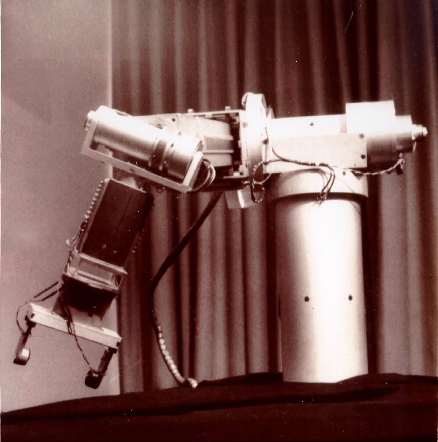
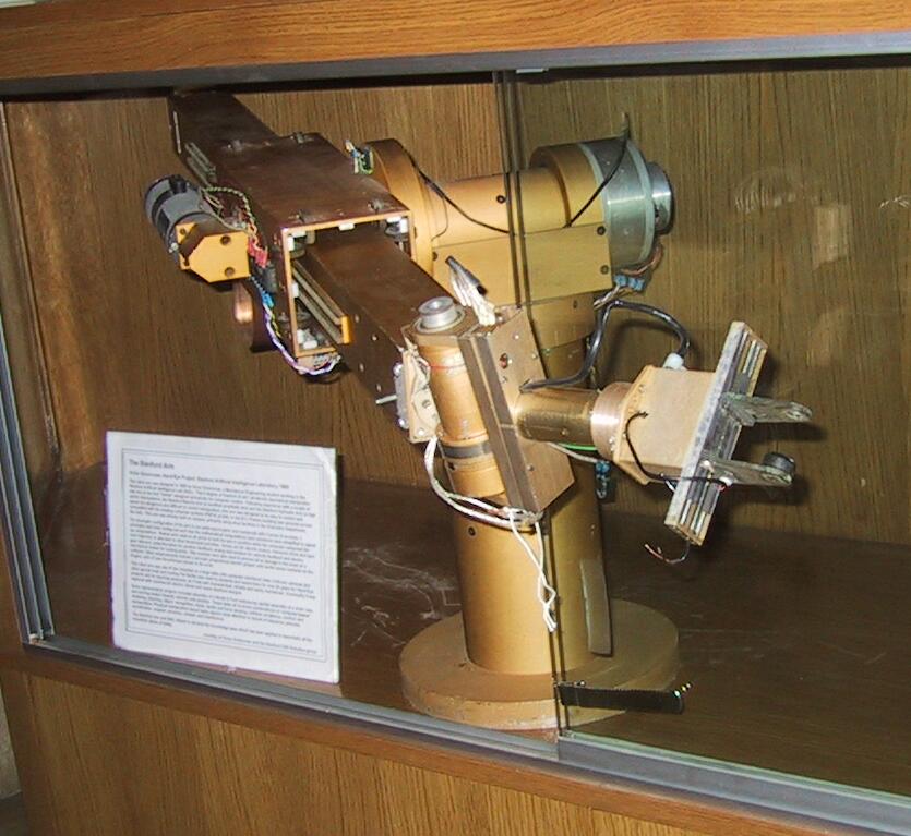
- Example of robot arm (Stanford Scheinman Arm)
- Reference
- Example of robot arm (Stanford Scheinman Arm)
- Reference
Direct(forward) Kinematics
- Mapping between the joint space of dimension n and the task space of manipulator of dimension m
- Called the "Geometric Model of the manipulator"
(It is determinded solely by knowing the geometry of manipulator)
- q(i) = ε'(i)θ(i) + ε(i)d(i)
- X = f(q)
- Mapping between the joint space of dimension n and the task space of manipulator of dimension m
- Called the "Geometric Model of the manipulator"
(It is determinded solely by knowing the geometry of manipulator)
- q(i) = ε'(i)θ(i) + ε(i)d(i)
- X = f(q)
3.3. Lecture 3: Inverse Kinematics 
Introduction
- Difficult task: Multiplicity or non-existence of potential soultions
- Problem: find q given T(B,W) or x / find q = f^(-1)(x)
- Difficult task: Multiplicity or non-existence of potential soultions
- Problem: find q given T(B,W) or x / find q = f^(-1)(x)
Closed Form Solutions
Algebraic: solution is found using the fact that θ1+θ2+θ3 = a0
Geometric: there are two possible solutions
Algebraic: solution is found using the fact that θ1+θ2+θ3 = a0
Geometric: there are two possible solutions
Piper's Solution
???
???
Existence of Solution
- If these two equations are correct, solution of the inverse kinematics exists
- However, sometimes there is no solution because of limitation of robot model
- If these two equations are correct, solution of the inverse kinematics exists
- However, sometimes there is no solution because of limitation of robot model
Workplace of the Manipulator
- Workspace: the set of points that can be reached with the mainpulator
- Joint limitation is always defined by the mechanical design of the manipulator
- Dextrous workspace: the set of points that can be reached by any possible orientation of the end-effector, important in the motion planning with obstacles (Reachable Workspace > Dextrous workspace)
- Workspace: the set of points that can be reached with the mainpulator
- Joint limitation is always defined by the mechanical design of the manipulator
- Related question: # of possible solutions
- Dextrous workspace: the set of points that can be reached by any possible orientation of the end-effector, important in the motion planning with obstacles (Reachable Workspace > Dextrous workspace)
# of Solutions
6R manipulator: 16 solutions
5RP manipulator: 16 solutions
4R2P manipulator: 8 solutions
3R3P manipulator: 2 solutions
in-parallel structures: 40 solutions
6R manipulator: 16 solutions
5RP manipulator: 16 solutions
4R2P manipulator: 8 solutions
3R3P manipulator: 2 solutions
in-parallel structures: 40 solutions

3.4. Lecture 4: The Jacobian 
Previous
- Establish the mathematical models which describe the relationships between the static configurations of a mechanism and its end-effector
- Establish the mathematical models which describe the relationships between the static configurations of a mechanism and its end-effector
Introduction
- Establish the relationship between δx and δq
- The relationship between δx and δq is described by the Jacobian matirx
- This matrix is key to the relationship between joint torques and end-effector forces
- Establish the relationship between δx and δq
- The relationship between δx and δq is described by the Jacobian matirx
- This matrix is key to the relationship between joint torques and end-effector forces
Differential Motion
- X = f(q)
Reference
- X = f(q)
Reference
3.5. Lecture 4: The Jacobian 
Previous
- Establish the mathematical models which describe the relationships between the static configurations of a mechanism and its end-effector
- Establish the mathematical models which describe the relationships between the static configurations of a mechanism and its end-effector
Introduction
- Establish the relationship between δx and δq
- The relationship between δx and δq is described by the Jacobian matirx
- This matrix is key to the relationship between joint torques and end-effector forces
- Establish the relationship between δx and δq
- The relationship between δx and δq is described by the Jacobian matirx
- This matrix is key to the relationship between joint torques and end-effector forces
Differential Motion
- X = f(q)
Reference
https://www.google.com/url?sa=i&rct=j&q=&esrc=s&source=images&cd=&ved=2ahUKEwjPvsirnazgAhWGdXAKHWlJCzYQjRx6BAgBEAU&url=https://ipfs.io/ipfs/QmXoypizjW3WknFiJnKLwHCnL72vedxjQkDDP1mXWo6uco/wiki/Jacobian_matrix_and_determinant.html&psig=AOvVaw0eZ7FwlFpMJW_0zd9038kk&ust=1549718461768195